PEMB drawings are the engineered drawing set a pre-engineered metal building manufacturer issues for one specific building: the design loads it was engineered for, the anchor bolt plan and reactions the foundation is designed around, the framing, bracing and connection details that define the steel, and the panel layouts and erection notes the crew builds from. The same set is what the customer reviews and approves before anything is fabricated.
Knowing what each sheet does makes that review worth doing, and knowing what the set leaves out avoids the most common surprise on a metal building project: foundation plans are not in it. For how the whole system fits together, start with our guide to the pre-engineered metal building.
What’s in a full set of PEMB drawings
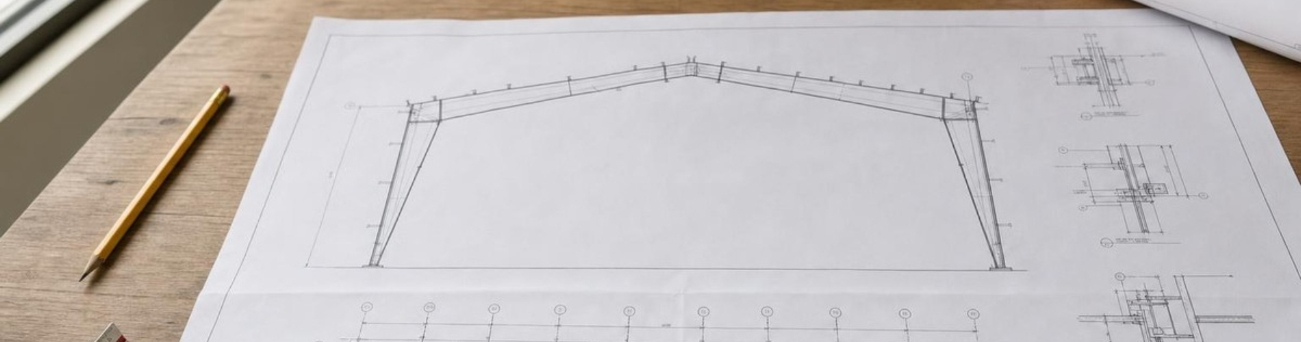
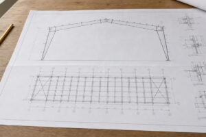
A full set of PEMB drawings covers the building from its design basis to its last panel. Stephen Tanco, Universal Steel’s owner, lists what a full set of structural drawings includes, and the sheets fall into eight groups by what each one is for.
| Group | What the sheets show | What it’s for |
|---|---|---|
| Design basis | Project information, building codes, design loads and criteria | The code and the loads the building was engineered to carry at its site |
| Foundation interface | Main frame reactions, anchor bolt plan | What the foundation engineer designs the foundation around |
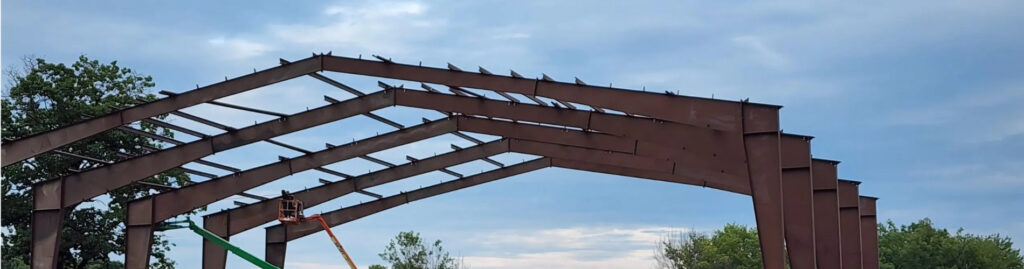
| Primary framing | Frame elevations, building cross sections, frame member sizes, bay spacing, column and rafter locations | The main frames and where each one stands |
| Secondary framing and bracing | Roof framing plan, wall framing plan, girt and purlin layout, roof and wall bracing plans | The members that carry the panels and keep the frames stable |
| Floors | Floor framing, floor joists | Mezzanines and other floor levels |
| Connections | Structural connection details, bolting requirements | How every piece joins, and the bolts each joint takes |
| Envelope | Roof and wall panel layout, panel profiles | Which panel goes where, and in what profile |
| Erection | Erection notes as required | Guidance the erector works from on site |
The design basis sheet carries more weight than its length suggests. Section 1603 of the International Building Code requires construction documents to show the size and location of structural members and the design loads behind them, including roof live load, snow, wind, earthquake data and the building’s risk category. Two buildings with the same dimensions on different sites carry different loads, so the design basis is where a set engineered for your site shows that it is.
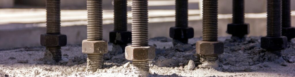
The anchor bolt plan is deliberately narrow. Under the MBMA Common Industry Practices, anchor rod plans prepared by the manufacturer are intended to show only the location, diameter and projection of the rods. Embedment and the foundation itself belong to the foundation engineer, which our guide to PEMB foundations covers in full. Our guide to the parts of a PEMB explains the framing members the plans refer to.
What isn’t in the set
A set of PEMB drawings covers the building the manufacturer engineers, and the foundation is not part of that building. Foundation plans are the point customers most often get wrong, as Stephen explains:
“Majority of the time clients think foundation plans would be included, but they are not. We only provide the anchor bolt layout plans.”
Stephen Tanco, owner, Universal Steel
The foundation is designed by the project’s foundation engineer, working from the anchor bolt layout plan and the main frame reactions in the set. Fabrication drawings are not part of the customer’s set either. Under the same industry practices, the manufacturer prepares fabrication drawings to make the steel but does not furnish them.
A downloaded or generic drawing is not a set for your building. Typical details and CAD files show what a metal building generally looks like, but they carry no one’s loads and no one’s site. The difference between a generic set and one engineered for a specific address is covered in our guide to PE-stamped drawings, along with what the engineer’s seal on a set certifies.
Why the sign-off matters
Signing off a set of PEMB drawings is a contractual step, not a formality. Under section 3.3.3 of the MBMA Common Industry Practices, a customer’s approval without changes affirms that the manufacturer has correctly interpreted the requirements in the order. Where the approved drawings and the order documents differ, the approved drawings take precedence.
Changes marked up on returned drawings are treated as a request to change the order, and they bind the manufacturer only once they have been agreed in writing. In practice, the approved drawings become the definition of the building that gets made.
At Universal Steel, the engineered drawings go to the customer for review and approval, and the building is released to fabrication once the customer signs a production waiver. The waiver is the last point at which changes can be made without refabricating steel, which our guide to how a PEMB gets built explains step by step.
What to check before you sign off
The check before sign-off is a comparison between the drawings and what you agreed to buy. Stephen’s advice is that the customer “should check everything before signing off” and “confirm the drawings match the contract and intended use.” In practice that means walking through six things:
- Overall building dimensions. Width, length and height against the contract.
- Doors and openings. Every door and framed opening, at the right size and on the right wall.
- Interior layout. Mezzanines and interior framing where the operation needs them.
- Roof and walls. The roof and wall systems and panels against what was ordered.
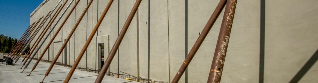
- Open wall conditions. Any wall left open for masonry or concrete, such as tilt-up panels, exactly where it was agreed.
- Intended use. The use on the design basis sheet, because use sets the building’s risk category and risk category sets the design loads.
The review is the time to raise a change, while it is still a correction to a drawing rather than a change to steel in production.
After approval: the drawings the site works from
Industry practice, set out in section 3.3.4 of the MBMA Common Industry Practices, is that once approval is given the manufacturer provides the final anchor rod plans, erection drawings and erection instructions. These are the documents the foundation contractor and the erector work from.
Erection drawings show where every component goes and how it connects. At Universal Steel, every piece is marked individually and cross-referenced on the erection drawings, so the crew can match steel to sheet. Erection drawings suggest a sequence and the connections, but they are not intended to specify the erector’s method, which remains the erector’s responsibility. Whether erection drawings must also be sealed depends on state rules and local requirements.
Frequently asked questions
What are construction details?
Construction details are enlarged drawings that show how the parts of a building join. In a set of PEMB drawings they are the structural connection details and bolting requirements that show how the frames, bracing and secondary members connect. Plans show where members go; details show how they fit together.
Are PEMB drawings the same as PE-stamped drawings?
PEMB drawings describe the whole set for a building, while PE-stamped drawings are drawings sealed by a licensed professional engineer who takes responsibility for the engineering on them. For a pre-engineered metal building, the structural drawings in the set are typically sealed by an engineer licensed in the state where the building will stand, which is why the two terms are often used for the same documents.
Can I download PEMB drawings?
Generic PEMB drawings and CAD details can be downloaded, but they are not drawings for a building. A real set of PEMB drawings is engineered for one building’s dimensions, use and site loads, and it comes from the manufacturer that engineers that building.
Read the set before you sign it
A set of PEMB drawings is the manufacturer’s statement of exactly what it will make: the loads, the frames, the connections and the panels, from the anchor bolts up. Read it against your contract and your intended use before you sign it, because once it is approved, the drawings define the building. See how Universal Steel engineers and manufactures its pre-engineered metal buildings for each project.